
Parameters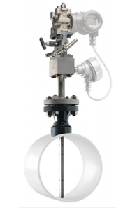
| Pipe Size | greater than 25 mm |
| Working Pressure | 320 bar max. for Gas and Liquid |
| 180 bar max. for Steam | |
| Temperature |
max 1200°C for Gas |
| max 590°C for Steam | |
| Accuracy | ±1 % of full scale |
| Output | 4~20mA, Pulse HART, MODBUS RTU |
| Material | 4~20mA, Pulse HART, MODBUS RTU |
| Options | Pressure and Temperature Compensation |
Working Principle
The pitot tube sensor is mounted perpendicular to the directon of the flow. The blue zone illustrates the velocity distribution insde the pipe. The flow at the sensor location is constricted and causes an increase of the flow velocity. This leads to a local overpressure zone in front of the sensor. In accordance, a low pressure zone forms at the backside of the sensor (suction side). The pressure transmitter converts the dfference into an electrical signal.
What Makes up a Complete Flow Measurement?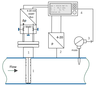
Fully configured dfferential pressure flow measurement section (example):
- Differental pressure sensor (sensor, 3-way manifold, differental pressure transmitter)
- Absolute pressure transmitter
- Pt100 temperature sensor (built into the protectvie case)
- Flow computer for pressure and temperature compensation
If the pressure and temperature change during operation the density will change. If the change of density is not compensated it will lead to inaccuracy of the flow measurement result. By the means of a temperature sensor (e.g. Pt100 sensor), an absolute pressure sensor and a flow computer the actual density can be calculated. The flow computer also usually compensates other quantites such as thermal pipe expansion.